6-DOF
Full constraint restored
25
Parts in live-line validation
1 wk
Post-install monitoring
Live
Running in production
CATIA V5NAAMS Components
DFMGD&T17-4 PH S.S.
In-House MachiningBOM / Sourcing
🔒
CATIA models, engineering drawings, and assembly screenshots are proprietary Tesla manufacturing IP and are not shown. This page describes the engineering problem, design approach, and decisions made.
The Problem
Constraint gap introduced by bowl feeder installation
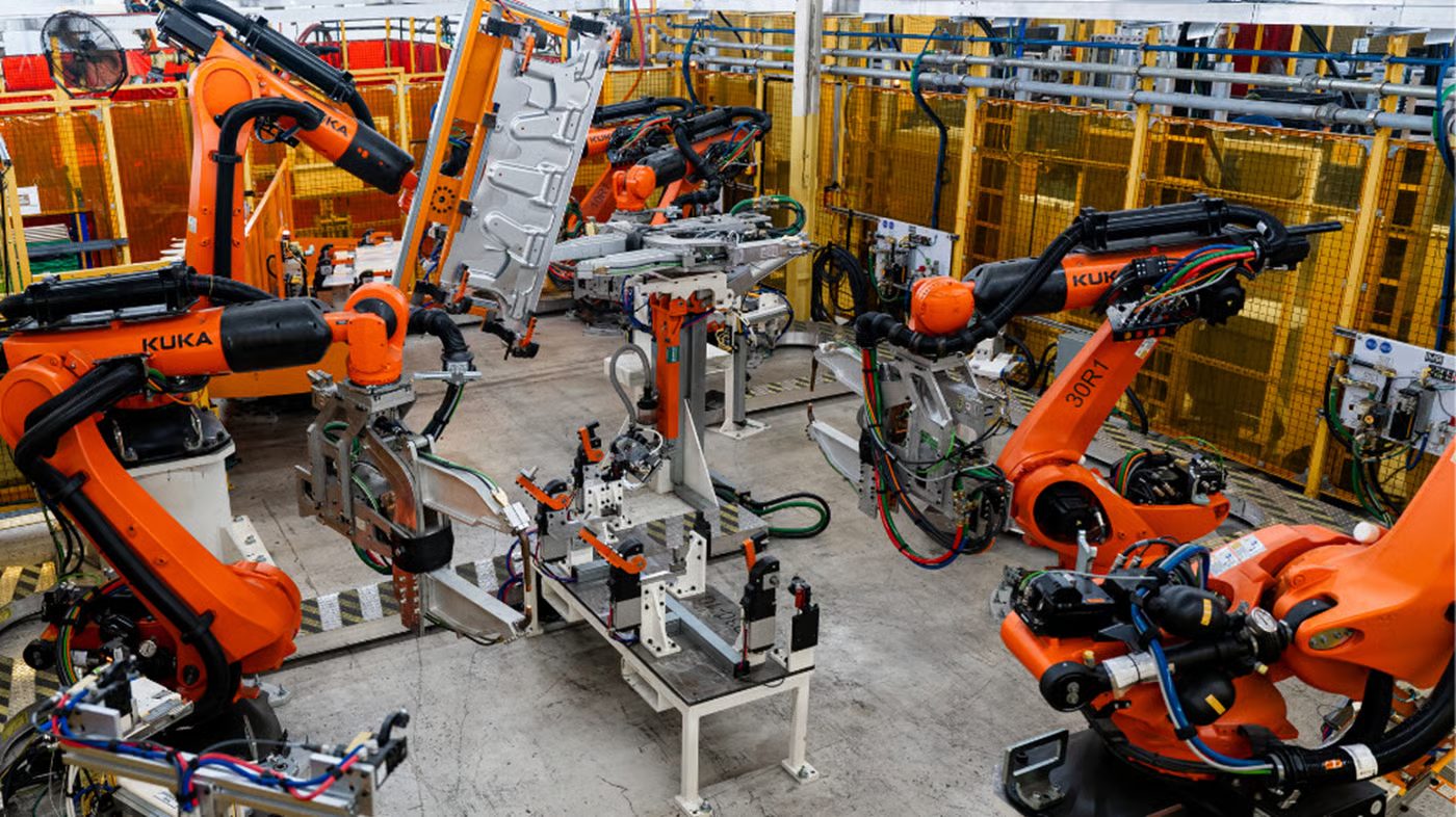
A bowl feeder was installed on the Model 3 body-in-white line to automate part feeding. The robot's end-of-arm tool had two locating features that together achieved full 6-DOF constraint on each part before placement. The bowl feeder's track architecture physically blocked one of those features — it had to be removed to allow the pick to happen at all. The remaining feature constrained rotation only. X-Y translation was now uncontrolled.
The robot was still completing cycles — the pick worked — but without positional constraint, part placement accuracy depended entirely on repeatability of the feed track exit position. Given cycle volume and downstream precision requirements, this was not a sustainable condition.
Design Requirements
- Restore full 6-DOF constraint on the part at pick — rotation already handled, new feature must control X-Y translation
- Clear feed track geometry — the new feature cannot reintroduce the physical conflict that forced the original removal
- No conflict at drop location — the feature must not interfere with part placement downstream; process analyzed carefully
- No robot program overhaul — offset adjustments acceptable, full path reprogramming is not
- Two shared variants plus one station-specific variant — geometry adapted per fixture family
- Gripper upper jaw redesign — insufficient clearance for locating pin insertion; jaw must be thinned and bolt holes countersunk flush
Design Solution
New locating feature restoring full constraint
Designed a new locating feature in CATIA V5 that pins X-Y translation while clearing the feed track geometry. Real-life measurements taken directly from the gripper and part to establish accurate reference geometry — no reliance on potentially outdated CAD assembly state alone.
Fixture Design
NAAMS configurable components
2 custom L-brackets — in-house machined
2 shared variants + 1 station variant
DFM-reviewed with fellow engineer
Gripper Upper Jaw
17-4 PH S.S. · ASTM A564 H1025
Thinned to clear pin insertion space
Bolt holes countersunk flush (CSK)
In-house machining
100+ parts picked daily
Process & Sourcing
BOM sourced from standard vendors
Machined, assembled, and installed on line
Drop location analyzed — no conflict
25-part live validation — no issues
1-week production monitoring with maintenance
- Real-life measurements taken from the physical gripper and part — used to validate CAD assembly state before committing to drawings
- Drop location process analyzed carefully — confirmed no downstream conflict introduced by new feature geometry
- Carried design through machining, finishing, assembly, and installation on the live line
- 25-part live-line validation with no issues, followed by one week of production monitoring with maintenance — no issues attributed to the new locating hardware
Production Validation
After installation, the tooling passed a structured validation sequence before full production release:
- Live-line trial: 25 consecutive parts with no constraint or placement issues
- Sustained monitoring: One week on production with maintenance oversight — no faults attributed to the new locating hardware
- Status: Hardware remained in production through roll-off with no locator-related issues during the monitoring window
Related Fix — Clamp Chamfer Redesign
During process analysis, an existing EOAT clamp was found interfering with weld beads on part ends — the contact face was too thick for clean engagement. Added a chamfer to thin the geometry at the clearance zone, machined in-house, and installed. Running in production.
Lessons Learned
Measure the real thing, don't trust the CAD alone
The assembly model had been modified by multiple people over time. Taking physical measurements from the actual gripper and part on the line caught a discrepancy between the CAD state and what was actually built — early enough that it didn't affect the drawings. On a live production tool, assuming the CAD is ground truth is a mistake.
Constraint analysis before design, not after
The original removal was done to solve the immediate feed track conflict without fully accounting for what that feature was doing kinematically. Understanding the full 6-DOF constraint picture first — what each feature controls, what happens if it's removed — is the analysis that should precede any design decision, not follow it.
Validate in production, not just on paper
The 25-part live trial and week-long monitoring with maintenance gave stakeholders confidence that the fix held under real cycle loads — not just in a design review. Production status is stronger evidence than a drawing package alone.