SolidWorks 2026SolidWorks API / PythonDesign for 3D PrintingTolerance & FitServo SizingCOTS IntegrationParallel GripperAllen-Bradley Micro820Arduino / C++Test Planning
⏳
Nothing on this page has been built or measured yet. The arm exists as a fully constrained native SolidWorks assembly with working joints, now at Revision D; every number below is a CAD-derived estimate or a design target, and is labelled as such. No parts have been printed and no hardware has been purchased. The Results table stays empty until it is filled from physical test data.
On a production floor I worked on tooling that a robot and a PLC already drove — I owned the mechanical end of the problem, not the sequencing, sensing, or fault handling around it. This project is the deliberate inverse: a cell small enough that I own every layer of it, from the locating scheme on the part to the state machine that decides when the gripper is allowed to close.
The whole cell is built around one pick object — an 8 × 22 × 7 mm 608ZZ bearing — located by an ID pin and rest at the pickup pose and a different datum scheme at the destination. Fixing the part first, then designing everything else to serve it, is the same order of operations that industrial fixturing follows, and it is what keeps the scope from drifting.
The single statement that decides whether this project worked:
Success criterion
The system shall autonomously detect, pick, transfer, and place a part for 50 consecutive cycles with at least 98% successful completion, documented fault handling, and measured positional repeatability.
Current CAD — Revision D
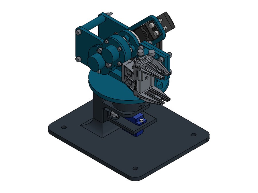
The prototype is a 4-DOF articulated arm: base yaw, shoulder pitch, elbow pitch, and a gripper. It is modelled natively in SolidWorks 2026 as editable parts and a real mated assembly — not a static arrangement of meshes — so joint travel can actually be exercised in CAD.
Revision D is the fourth pass, and it changed the architecture rather than the details. The printed single-finger gripper is gone, replaced by a purchased parallel gripper on a removable printed fork, so the tool is now a swappable interface instead of part of the arm. Both pitch joints moved to MG996R servos sharing one common horn interface — the same OD20 / PCD14 metal horn and 32 mm standoff spacing at the shoulder and the elbow — and the old single yaw-platform-plus-upright part was split into a separate platform and a bolt-on upright so each one prints and services independently.
Isometric — full assembly. Base pedestal and bolt-down plate, yaw platform on a stacked 608ZZ pair, removable yaw-servo cassette underneath, and the parallel gripper carried on the modular forearm.Front — home pose, jaws open. Shoulder and elbow each run on a steel dowel through a printed adapter into a 608ZZ, so the servo horn carries torque and the bearing carries the radial load. Jaw opening is a driven equation, 0–32 mm.Right — joint stack. Two MG996R cases stacked outboard, 32 mm standoffs setting both cheek spacings, and the gripper fork bolted to the forearm through four M3×16. The outboard mass here is what costs the shoulder its margin.
Assembly at a glance
198 total components · 207 mates
15 printed part types · 23 instances
45 explicitly modelled fastener stacks
64 constrained sketches across the 6 new parts
637 g modelled mass at solid-print density
Parts, mates and fastener stacks were built and audited through the SolidWorks API with Python, so the counts above come out of the model rather than out of a spreadsheet.
Design Decisions
Joint Architecture
Servo horn takes torque only
608ZZ bearings take radial load
6.35 × 25.4 mm steel dowels as pivots
Printed dowel-to-8 mm-bore adapters
Screwed keepers for axial retention
Serviceability
Removable yaw servo cassette
Yaw platform and upright are separate bolt-on parts
Gripper fork unbolts as a unit (4 × M3×16)
One horn interface serves both pitch joints
Crush spacers stop the tool ears clamping inward
Sizing Basis
20 g payload target (provisional)
Solid-density mass bound, 1.25 load factor
Budget = ⅓ of reference stall torque
Shoulder margin 1.15× — the binding constraint
Elbow margin 3.60× on the second MG996R
0.65 N per jaw needed at µ = 0.3
Reference ratings, not measured torque
The bearing does the work the horn shouldn't. A servo output shaft is not a structural bearing. Every pitch joint pairs the horn with a dowel running in a 608ZZ, so the horn only ever sees torque — the reason the joints grew cheeks, standoffs and keepers instead of bolting a link straight to a horn.
Buying the gripper was the right call, and I resisted it for three revisions. A printed single-finger jaw closing on a round bearing was always going to be the least repeatable part of the cell. A purchased parallel gripper gives true parallel jaws, a 32 mm driven stroke and its own feedback servo for $29.95 — cheaper than the print time I had already spent failing to match it. The design effort moved to the interface: a removable fork, the real 4.2 mm jaw axes, M4×35 through-bolts, and two 13 mm crush spacers inside the 13.4 mm ear gaps so tightening cannot squeeze the tool body.
One horn interface, two joints. Both pitch joints now use the same OD20 / PCD14 metal horn on 20.5 mm spacing with 32 mm standoffs. That is what closed the horn-interface hold below: instead of reconciling three different horn patterns, there is one pattern to get right, and getting it right fixes both joints.
Joint travel was verified in the native model, not eyeballed. A separate configuration suppresses the command mates and enforces angle limits: yaw ±60°, shoulder −15° to +80°, elbow −100° to −5°, with jaw opening driven 0–32 mm by equation. Six saved pose configurations reopen with zero mate errors, all 198 references resolving and no part feature errors.
23 of 24 sampled poses are clean. Ten motion poses and fourteen lift/yaw transfer samples were checked by driving the native angle dimensions and independently comparing every component transform against the kinematics. The one exception is 0.18 mm³ of overlap inside the purchased gripper's own imported geometry when it is commanded fully shut to 0 mm — supplier model artefact, no printed part involved, and not a pose the tool needs.
The shoulder range shrank, and that is a real cost. The larger elbow servo case fouls the platform sooner, so the shoulder lower limit moved from −30° to −15°. Combined with 637 g of modelled mass on a 150 mm lever, the shoulder margin fell from 2.15× to 1.15×. It still clears the ⅓-of-stall budget, but it is now the number that decides whether this arm works.
Those checks are discrete samples, not a swept proof. Continuous sweep, cable routing, tool access and external fixtures are still excluded — which is why an earlier pickup pose turned out to clip the yaw platform and had to be revised.
Structure is PETG. Printed at the WashU makerspace; a dedicated fit coupon is exported alongside the parts so the dowel and bearing fits get trialled before a full set is printed.
Horn Interface — Closed
The problem, as it stood at Revision B
The shoulder was modelled against a nominal 26 mm horn plate on a 20 mm bolt circle. The metal disc horn actually sold for this servo class is 20 mm OD on a 14 mm bolt circle — it would not drop into the modelled pattern, and substituting it also shifted the axial stack by about 2.5 mm. Every horn-connected part was held from release, and three different horn patterns across four servos meant three separate interfaces to reconcile.
How Revision D closed it
Both pitch joints were standardised onto the real OD20 / PCD14 M3-tapped metal horn — the part that is actually sold — at 20.5 mm spacing on 32 mm standoffs, and the printed links were rebuilt around it rather than around a nominal envelope. Dropping the printed gripper removed a fourth horn interface entirely. What was three mismatched patterns is now one measured pattern used twice, and the supplier drawing is saved next to the model in source-reference/.
This is worth stating plainly because it is the whole argument for modelling properly before printing: the mismatch was found by a CAD check, cost four revisions of rework, and cost no material and no money. Finding it with a printed link and a bag of the wrong screws is the alternative. Seated horn height and the bearing/dowel fits are still assumptions — those need calipers on the real parts, not another revision.
Open Problems
Shoulder margin · 1.15×
Two MG996R cases and a 30 g tool sit outboard on a 150 mm lever, and modelled mass is up to 637 g. Against a budget of one third of reference stall torque the shoulder now has 1.15× where Revision B had 2.15×. That is a CAD estimate built on a solid-density mass bound and a datasheet rating, so the true figure could fall either side of it — which is exactly why it has to be measured on the built arm before anything downstream is trusted.
Tool availability
The gripper is a $29.95 candidate that the supplier showed as backordered on 2026-09-12, and nothing has been purchased. The fork adapter is built around its published STEP and dimension drawing rather than a measured unit, so the interface is verified against the supplier's geometry, not against hardware in hand.
Plan to Validation
Four phases, each independently demonstrable. No phase starts before the previous one has measured results — the failure mode for a project like this is fragmenting it into five half-finished subsystems.
Phase
Goal
Demonstrable output
Status
1 — Mechanical proof
Printed arm, one pick object, defined pickup and place poses, repeatable hard stops
Manual cycle with basic repeatability data
CAD in progress
2 — Motion & sensing
Arduino motion control, home switch, part-present sensor, end-position confirmation
Repeatable automatic pick-and-place cycle
Not started
3 — PLC supervisory control
Micro820 owns cycle start, permissives, state sequence, faults, reset and the handshake; the motion controller owns low-level movement
The PLC-to-motion-controller split is deliberate. Letting the PLC supervise a separate motion controller over a simple I/O handshake is how a real cell is partitioned, and it is the part of automation I had the least ownership of on the floor.
Results
Empty until measured. This table gets filled from the test plan, not from expectations.
Metric
Target
Measured
Successful pick rate
≥ 98% over 50 cycles
—
Positional repeatability
Set after Phase 1
—
Cycle time
Set after Phase 2
—
Payload
≥ 20 g
—
Gripper retention through transfer
No drops across the validation run
—
What I've Learned So Far
Lock the part before you design the machine
Choosing the 608ZZ first — and writing down how it gets located at both ends of the cycle — is what made every later decision decidable. Jaw geometry, payload, Z clearance over the pin, and the sensor choice all fall out of that one commitment. The scope only started converging once the part stopped being a variable.
A model that can't move hasn't been checked
Building real mates instead of a fixed arrangement is slower, and it is what caught the pickup pose colliding with the yaw platform. Driving the joints through named angle dimensions and then independently comparing all 198 component transforms against the kinematics turns "it looks fine" into a check that either passes or does not.
Four revisions to admit the right part was for sale
Revisions A through C all had a printed single-finger gripper, and each one made it slightly better without making it good. Swapping to a $29.95 parallel gripper solved repeatability, stroke and feedback in one move, and turned the interesting problem into an interface problem — mounting, crush spacers, fastener access — which is the problem worth having. Knowing which parts to design and which to buy is a judgement call, and I got it wrong for three passes.
Every improvement spends something
The second MG996R and the purchased tool made the arm more capable and more serviceable. They also added 119 g, moved mass outboard, cut the shoulder's usable range from −30° to −15°, and halved its torque margin. Nothing about Revision D is free, and writing down what it cost is the only way the next revision starts from the truth rather than from the highlight reel.
Separate what you assumed from what you measured
The load report labels every input: CAD solid volume, manufacturer reference mass, assumed friction coefficient. The torque margins are real conclusions from those inputs, but they are not test data, and writing them down that way keeps me from quoting a 1.15× margin as if a servo had actually been loaded. The same discipline is why the Results table above is still blank.